Motor 2040 - Quad Motor Controller
by Pimoroni


A compact 4 channel motor+encoder controller, powered by RP2040. It has RGB and per-motor indicator LEDs plus built in voltage and current sensing.
Motor 2040 is a standalone motor controller for driving motors with encoders attached. Encoder motors can provide feedback to the controller, enabling more precise control over position and velocity - perfect for building a four wheel drive robot rover or buggy (add mecanum omniwheels to go sideways!). We've built the RP2040 chip right into Motor 2040 so you don't need separate microcontroller and driver boards, keeping everything tidy and lightweight.
Why limit yourself to vehicular constructs though, you could use it as the brains of any project that involves motors: elaborate pulley systems, 1:12 replicas of It's A Small World or even customisable dials with haptic feedback and programmable endpoints.
Motor 2040 comes with many useful built-in bells and whistles, such as:
- An addressable RGB LED (AKA Neopixel) for visual feedback and status reports.
- A pair of mono indicator LEDs on each motor channel to show you when and in what direction a motor is moving. This helps visualise what your code is doing and means you can prototype without having motors plugged in!
- A QW/ST connector to make it easy to attach Qwiic or STEMMA QT breakouts - great for adding some sensor smarts.
- Some neat voltage/current/fault sensing features to help prevent motor mishaps.
It's supported by a well documented C++/MicroPython motor and encoder library with lots of examples to show you how to use the individual features (and everything together).
Motor 2040 and MMME shims
We've designed Motor 2040 to interface easily with our new MMME (Micro Metal Motor Encoder) shims which can be used to upgrade our standard Micro Metal Motors into fancy encoder motors. We also sell motors with MMMEs pre-attached, if you want to skip the soldering.
Once your motor has an MMME attached to it you can plug it into Motor 2040 with a 6 pin JST-SH cable. Convenient!
Motors, shims and cables are sold separately.
Features
- Powered by RP2040 (Dual Arm Cortex M0+ running at up to 133Mhz with 264kB of SRAM)
- 2MB of QSPI flash supporting XiP
- 2 Dual H-Bridge motor drivers (DRV8833)
- 4 JST-SH connectors (6 pin) for attaching motors
- Wide voltage range for motors and logic (2.7V to 10V)
- On-board 3V3 regulator with input up to 13.2V (max regulator current output 150mA)
- Onboard voltage, current and fault sensing
- Per motor current limiting (0.5A) *
- Per motor direction indicator LEDs **
- Addressable RGB LED/Neopixel
- Reset and BOOT button (the BOOT button can also be used as a user button)
- USB-C connector for programming and power (3A max)
- Qw/ST (Qwiic/STEMMA QT) connector for breakouts
- Fully-assembled
- C++/MicroPython libraries
- Schematic
- Dimensional drawing
Software
Because it's a RP2040 board, Motor 2040 is firmware agnostic! You can program it with C/C++, MicroPython or CircuitPython.
Our C++/MicroPython libraries will help you get the most out of Motor 2040, they're packed with powerful features for working with motors. You'll get best performance using C++, but if you're a beginner we'd recommend using our batteries included MicroPython build for ease of getting started.
- Download Pirate brand MicroPython (you'll need the 'pico-vx.x.x' image)
- MicroPython API documentation
- MicroPython examples
- C++ examples
You can also use CircuitPython on your Motor 2040, if you want access to all the nice conveniences of Adafruit's ecosystem.
- Download CircuitPython for Motor 2040 (coming soon)
- Getting Started with CircuitPython
- CircuitPython examples
If you'd like to program Motor 2040 from an Android phone then you could try the DroidScript app, available on Google Play. You'll need a USB-C cable and a recent version of our MicroPython firmware installed on the board.
Connecting Breakouts
If your breakout has a QW/ST connector you can plug it in directly with a JST-SH to JST-SH cable, or you can connect older I2C Breakout Garden breakouts with a JST-SH to JST-SH cable coupled with a Qw/ST to Breakout Garden adaptor.
- List of breakouts currently compatible with our C++/MicroPython build.
Powering Motor 2040
Motor 2040 can be powered either by plugging the board into a USB-C power source (like a PC or power bank) or by connecting a battery pack to the EXT PWR or VSYS connections. On an unmodified board, you should only have one power source connected at a time, to avoid back-powering your computer or battery.
If you want to have two power sources connected at the same time, Motor 2040 has two traces on its underside that you can cut to do this safely.
- Cut EXT PWR to VSYS if you want to provide your motors with a separate power supply (up to 10V) from that used to power the rest of the board. Board power (up to 13.2V) will need to be provided either by USB 5V or VSYS.
- Cut USB 5V to VSYS if you want to run the board entirely off a separate power supply, without worry of back-powering your computer. Note that this also means the board will not turn on when only connected by USB.
Below is a simplified circuit diagram showing the power wiring:

Notes
- Measurements: 52mm x 38mm x 7.7mm (L x W x H). The mounting holes are M2.5 and 2.7mm in from each edge.
- * The current limit of each motor can be disabled by soldering the "high current" pads on the rear (doing this will also disable the current monitoring). The maximum supported output current when unlimited is 1.2 A continuous (2 A peak) per motor.
- ** The direction indicators for each motor can be disabled by cutting the "motor LED" traces on the rear.
- The pinout of the JST-SH motor connectors is M+, M-, 3v3, A, B, GND.
- Motor 2040 has some extra broken out headers that adventurous roboticists might find useful (note that these are unpopulated and so will require soldering):
- 2 sets of headers for connecting analog sensors
- 1 set of headers for connecting a serial device, or an 3.3V ultrasonic distance sensor
- Unpopulated screw terminals for supplying external power (10A max continuous current)
- Exposed analog, Breakout Garden and debug pins
About RP2040
Raspberry Pi's RP2040 microcontroller is a dual core ARM Cortex M0+ running at up to 133Mhz. It bundles in 264kB of SRAM, 30 multifunction GPIO pins (including a four channel 12-bit ADC), a heap of standard peripherals (I2C, SPI, UART, PWM, clocks, etc), and USB support.
One very exciting feature of RP2040 is the programmable IOs which allow you to execute custom programs that can manipulate GPIO pins and transfer data between peripherals - they can offload tasks that require high data transfer rates or precise timing that traditionally would have required a lot of heavy lifting from the CPU.
-
Motor 2040 - Quad Motor Controller
PIM618£20.00
MMMEs with motors
-
 Micro Metal Gearmotor with Encoder (MMME) – 50:1 Regular+ £8.25
 -
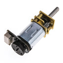 Micro Metal Gearmotor with Encoder (MMME) – 50:1 Sideways+ £8.25


USB and motor cables
-
 USB-A to USB-C Cable – 1m+ £3.25
 -
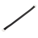 6 Pin JST-SH Cable – 100mm (Pack of 4)+ £2.50


Wheels and other useful things
-
 Micro Metal Gearmotor to LEGO® Axle Adaptor (pack of 4)+ £3.25
 -
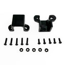 Long Micro Metal Gearmotor Bracket (pack of 2)+ £3.25


Power options
-
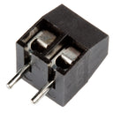 3.5mm Screw Terminal High-Temperature (pack of 10) – 2-Pole+ £2.50

Shop with confidence – we've been serving the hobbyist electronics, Maker, and retro gaming communities since 2012.
- Satisfaction or refund guarantee
- Worldwide shipping via mail or courier
- 58,000+ customer reviews
- Secure website and payments
