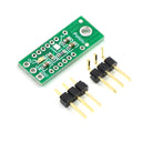
Pololu Carrier for Sharp GP2Y0D815Z0F, GP2Y0D810Z0F, and GP2Y0D805Z0F Sensors
by Pololu


This tiny carrier board makes it easy to integrate a Sharp digital distance sensor into your project by providing all of the required external components, an LED for feedback about the output state, and a 0.1″-pitch, three-pin interface to the sensor.
The GP2Y0D805, GP2Y0D810 , and GP2Y0D815 are Sharp’s smallest and fastest distance sensors, and this tiny carrier board for these sensors includes all of the external components required to make them work. With detection distances up to 150 mm and a typical sampling rate of almost 400 Hz, these sensors provides an attractive alternative to shorter-range LED-phototransistor reflectance pairs and longer-range but slower sensors such as the Sharp GP2Y0A41SK0F analog distance sensor.
However, these sensors require external components and have a non-standard 1.5 mm pitch, which can make them difficult to integrate into projects based on a 0.1″ pitch. This carrier board includes these components and provides a 0.1″-pitch, three-pin interface: ground, power, and output.
Using the carrier board
You will need to solder the sensor to the carrier board so that the solder connections are made on the component-side of the board and the sensor package presses against the component-free side of the board. Once the sensor is soldered in, the Pololu carrier board lets you interface with the GP2Y0D815, GP2Y0D810, or GP2Y0D805 sensor using a three-pin 0.1″ connector.
The square pad is ground, the middle pad is VIN (2.7 – 6.2 V), and the remaining pad is the sensor output, OUT. Depending on your power source, you might notice an increase in performance by placing a large (>10 uF) capacitor between power and ground somewhere near the sensor.
A red LED on the back of the PCB lights when the output is low, indicating that the sensor is detecting something. If so desired, you can disable this LED by cutting the trace between it and the OUT pin where it is marked on the silkscreen or by desoldering the LED.
The GP2Y0D815Z0F, GP2Y0D810Z0F, and GP2Y0D805Z0F have an optional enable input that can be used to put the sensor into low-power mode. The Pololu carrier board connects this input to Vcc so that the sensor is always enabled, but you can solder a wire to the pad labeled “enable” on the back of the PCB if you want control over this input. Note that you will need to cut the trace that connects the enable line to Vcc on the PCB if you want to be able to disable the sensor. This trace is marked on the silkscreen, and there is a caret that indicates where we suggest you make the cut.
The carrier board has a 0.086″ mounting hole for a #2 or M2 screw. You can make the module more compact by cutting or grinding off this portion of the PCB if you do not need the mounting hole.
We no longer stock this product
It's sad to say goodbye but sometimes we have to retire products to make way for new things.
You may still be able to buy this product directly from our friends at Pololu - check out their website!
Shop with confidence – we've been serving the hobbyist electronics, Maker, and retro gaming communities since 2012.
- Satisfaction or refund guarantee
- Worldwide shipping via mail or courier
- 57,000+ customer reviews
- Secure website and payments
