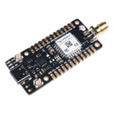
LoRa-E5 mini
by Seeed Studio


LoRa-E5 mini is a compacted-sized dev board suitable for rapidly testing and building a small-size LoRa device and application prototyping.
LoRa-E5 mini is embedded with and leads out full GPIOs of LoRa-E5 STM32WLE5JC. It has rich interfaces including UART, ADC, SPI, IIC,etc. Supporting LoRaWAN protocol and global frequency, LoRa-E5 mini is able to achieve a transmission range of up to 10 km in open area and ultra-low power consumption.
Features
- Full GPIOs led out from the Lora-E5 STM32WLE5JC
- Global LoRaWAN® and LoRa frequency plan supported
- Long-distance transmission range to 10km (ideal value in open area)
- Mini and compact size, suitable for rapid testing and building small size prototype
- Convenient RESET and BOOT buttons on board
LoRa-E5 mini is a compact development board suitable for the rapid testing and building of small-size prototyping and helps you design your ideal LoRaWAN wireless IoT device with a long-distance transmission range.
LoRa-E5 mini is embedded with the LoRa-E5 STM32WLE5JC Module, which delivers the world-first combo of LoRa RF and MCU chip into one single tiny chip and is FCC and CE certified. It is powered by ARM Cortex-M4 core and Semtech SX126X LoRa chip and supports LoRaWAN protocol on the worldwide frequency and (G)FSK, BPSK, (G)MSK, and LoRa modulations. (Learn more about LoRa-E5)
LoRa-E5 mini leads out all GPIOs of LoRa-E5, including UART, ADC, SPI, IIC, etc. It contains RESET and BOOT buttons and is user-friendly. Supporting LoRaWAN protocol, LoRa-E5 mini features ultra-long-range transmission and ultra-low power consumption: it is able to achieve a transmission range of up to 10 km, and the sleep current of LoRa-E5 modules on board is as low as 2.1 uA(WOR mode). It is designed with industrial standards with a wide working temperature at -40 ℃ ~ 85℃, high sensitivity between -116.5dBm ~ -136 dBm, and power output up to +20.8 dBm at 3.3V.
Since LoRa-E5 is a LoRaWAN chip with an MCU, there are three main ways to utilize the LoRa-E5 mini:
- Connect LoRa-E5 mini to PC and control by AT commands
- There is a built-in USB to UART function on board, you could connect the LoRa-E5 mini to your PC with a USB type C cable, and use serial communication software to send AT commands and read data from the board.
- For example, connect LoRa-E5 mini to Seeeduino XIAO and the Expansion Board via UART, and send AT commands and read data from Seeeduino XIAO through Arduino IDE serial monitor.
- Develop your own LoRa development board with MCU function by using STM32Cube Programmer, which is the SDK officially provided by STMicroelectronics. To download this SDK resource, please find the resources linked below.
With all the outstanding features listed above, the LoRa-E5 mini will be a superior choice for IoT device development, testing, prototyping, and applications in long-distance, ultra-low power consumption IoT scenarios like smart agriculture, smart office, and smart industry.
If you are unfamiliar with LoRa and LoRaWAN technology, please check out this blog LoRapedia in detail.
Application Note
For more detailed information about how to use LoRa-E5, please visit LoRa-E5 (STM32WLE5JC) Module Wiki.
1. Factory AT Firmware
LoRa-E5 series has a built-in AT command firmware, which supports LoRaWAN Class A/B/C protocol and a wide frequency plan: EU868/US915/AU915/AS923/KR920/IN865. With this AT command firmware, users can easily and quickly build their prototype or application.
The AT command firmware contains a bootloader for DFU and the AT application. The "PB13/SPI_SCK/BOOT" pin is used to control LoRa-E5 to stay in the bootloader or jump to the AT application. When PB13 is HIGH, the module will jump to AT application after reset, with a default baud rate of 9600. When PB13 is LOW (press the "Boot" button on LoRa-E5 Dev Board or LoRa-E5 mini), the module will stay in the bootloader, and keep transmitting "C" character every 1S at baud rate 115200.
Attention
- Factory AT Firmware is programmed with RDP(Read Protection) Level 1, developers need to remove RDP first with STM32Cube Programmer. Note that regression RDP to level 0 will cause a flash memory mass to erase and the Factory AT Firmware can't be restored again.
- The "PB13/SPI_SCK/BOOT" pin on the LoRa-E5 module is just a normal GPIO, not the "BOOT0" pin of the MCU. This "PB13/SPI_SCK/BOOT" pin is used in the bootloader of the Factory AT firmware, to decide to jump to APP or stay in bootloader(for DFU). The real "BOOT0" pin doesn't pinout to the module, so developers need to be careful when developing low-power applications.
2. Clock Configuration
2.1 HSE
- 32MHz TCXO
- TCXO power supply: PB0-VDD_TCXO
2.2 LSE
- 32.768KHz crystal oscillator
3. RF Switch
LoRa-E5 module ONLY transmits through RFO_HP:
- Receive: PA4=1, PB5=0
- Transmit(high output power, SMPS mode): PA4=0, PB5=1
Specifications
| Parameters | Specifications |
|---|---|
| size | 50 x 23mm |
| voltage - supply | 3.7V - 5V |
| power - output | up to +20.8 dBm at 3.3V |
| working frequency | 868/915MHz |
| protocol | LoRaWAN |
| sensitivity | -116.5 dBm ~ -136 dBm |
| interfaces | USB Type C / 2P-2.54mm Hole / 1*12P-2.54mm Header*2 / SMA-K / IPEX |
| modulation | LoRa, (G)FSK, (G)MSK, BPSK |
| working temperature | -40℃ ~ 85℃ |
| current | LoRa-E5 module sleep current as low as 2.1uA (WOR mode) |
Part List:
- LoRa-E5 mini x1
- Antenna(EU868/US915) x1
- USB TypeC (20cm) x1
- Sticker x1
- 1X12pin male pin headers x2
Documentation
- LoRa-E5 mini Datasheet:
- LoRa-E5 Datasheet:
- LoRa-E5 Certifications:
- LoRa-E5-HF Certification CE-VOC-RED
- LoRa-E5-HF FCC Certification -DSS
- LoRa-E5-HF FCC Certification -DTS
- Relevant SDK:
-
LoRa-E5 mini
SEEED-113990939Out of stock£20.00
Shop with confidence – we've been serving the hobbyist electronics, Maker, and retro gaming communities since 2012.
- Satisfaction or refund guarantee
- Worldwide shipping via mail or courier
- 57,000+ customer reviews
- Secure website and payments