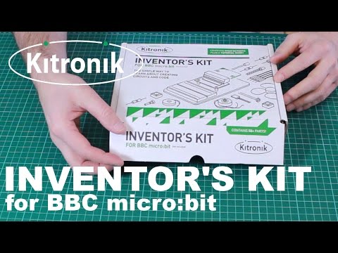
Inventor's Kit for the micro:bit
by Kitronik


Get more from the micro:bit with Kitronik's incredible inventor's kit! The simple way to learn about creating circuits and code.
Please note: micro:bit is NOT included.
The Kitronik Inventor's Kit for the micro:bit is a great way to get started with programming and hardware interaction with the micro:bit. This Inventor's Kit contains everything you need to complete 10 experiments including using LEDs, motors, LDRs, and capacitors.
To get you off to a flying start, Kitronik have included an easy to follow tutorial book which guides you through everything you will need to know about programming the micro:bit. You don't need any experience with programming as the tutorial book will guide you every step of the way. You'll be programming and creating circuits in no time!
The Kitronik Inventor's Kit for the micro:bit provides a fantastic way of learning how to construct and control electronic circuits. The micro:bit has a selection of pins that are located on the bottom edge of its PCB (see datasheet below for details). By using the specially designed edge connector board for the micro:bit in conjunction with the breadboard (see below), it is easy to use these pins to connect additional components to the micro:bit.
No soldering is required and you can build your first circuit in minutes!
Note:
- This kit requires assembly
Features:
- No soldering required - build your first circuit in minutes!
- Make 10 experiments included in the provided step-by-step tutorial book
- All parts are included to conduct the 10 experiments (listed below)
- Breaks out 21 accessible pins from the micro:bit using the edge connector board for the micro:bit (included)
- Small prototype breadboard included for fast prototyping
- Compatible with micro:bit v1 and v2!
All of the experiments included in this booklet (listed below) are based on the Microsoft BlockEditor and Microsoft TouchDevelop editor software.
Experiments included in the tutorial book:
- Experiment One: Say 'Hello' to the micro:bit
- Experiment Two: Using an LDR & analog inputs
- Experiment Three: Dimming an LED using a potentiometer
- Experiment Four: Using a transistor to drive a motor
- Experiment Five: Using the accelerometer to control motor speed
- Experiment Six: Setting the tone with a piezo buzzer
- Experiment Seven: Wind power
- Experiment Eight: Making a game using the compass
- Experiment Nine: Capacitor charge circuit
- Experiment Ten: Using an RGB LED
Contents:
- 1 x Perspex mounting plate
- 1 x potentiometer & finger adjust spindle
- 2 x plastic spacer 10mm
- 1 x sticky fixer for battery pack
- 1 x small prototype breadboard
- 1 x terminal connector
- 4 x push switch
- 1 x motor
- 1 x transistor
- 2 x red 5mm LED
- 2 x orange 5mm LED
- 2 x yellow 5mm LED
- 2 x green 5mm LED
- 1 x RGB 5mm LED
- 1 x fan blade
- 5 x 2.2KΩ resistor
- 5 x 10KΩ resistor
- 5 x 47Ω resistor
- 1 x edge connector breakout board for micro:bit
- 1 x miniature LDR
- 10 x male to male jumper wires
- 10 x male to female jumper wires
- 1 x 470uF electrolytic capacitor
- 1 x piezo element buzzer
- 4 x pan head M3 machine screw
Requires:
- 1 x micro:bit
- 1 x Phillips screwdriver
- 1 x terminal block screwdriver
- 1 x micro USB cable
-
Inventor's Kit for the micro:bit
KIT-5603£21.00
Essential accessories
-
 micro:bit accessories kit+ £3.50

Lovely add-on kits
Want to take your micro:bit journey a little further? Then these kits are for you!
Shop with confidence – we've been serving the hobbyist electronics, Maker, and retro gaming communities since 2012.
- Satisfaction or refund guarantee
- Worldwide shipping via mail or courier
- 53,000+ customer reviews
- Secure website and payments