Tiny 2350
by Pimoroni


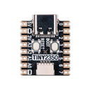
A postage stamp sized RP2350 development board with a USB-C connection, perfect for portable projects, wearables, and embedding into stuff.
While we love the Raspberry Pi Pico we also wanted something smaller and with a bunch more flash on board. Introducing the Tiny 2350 - a teeny tiny powerhouse with the chops to realise truly ambitious projects.
Programmable via USB-C, Tiny 2350 comes with 4MB of flash storage on board. The board is designed with castellated pads to allow it to be directly soldered onto a PCB (or you can attach pin headers to hook it up on a breadboard or connect things to it directly with wires). We've also managed to fit in a programmable RGB LED, a reset button, a Qw/ST connector for connecting up I2C devices and some clever circuitry that lets you use the boot button as a user controllable switch.
It's compatible with firmware built for the Raspberry Pi Pico 2 but offers a reduced number of pins due to its size. You can even run MicroPython on it!
Due to popular demand, we've now also got headered Tiny 2350s available, with downwards pointing pin headers lovingly pre-soldered by pirates.
Features
- Powered by RP2350A (Dual Arm Cortex M33 running at up to 150MHz with 520KB of SRAM)
- 4MB of QSPI flash supporting XiP
- USB-C connector for power, programming, and data transfer
- User controllable RGB LED
- Qw/ST (Qwiic/STEMMA QT) connector for attaching breakouts
- Twelve IO pins (including four 12-bit ADC channels)
- Reset and BOOT buttons (the BOOT button can also be used as a user button)
- On-board 3V3 regulator (max regulator current output 300mA)
- Input voltage range 3V - 5.5V
- Programmable with C/C++ or MicroPython
- Dimensions: approx 22.9 x 18 x 5.8mm (L x W x H, including the USB-C port)
Pinout and Schematic
Getting Started
If you're new to RP2040/RP2350 boards then we think our custom MicroPython build is the easiest way to get started. Check out our Learn guide for a beginner friendly introduction:
You can find MicroPython firmware and example code at the links below:
Or, if you'd prefer to use CircuitPython on your Tiny 2350, you can:
Connecting Breakouts
If your breakout has a Qw/ST connector on board, you can plug it straight in with a JST-SH to JST-SH cable, or you can easily connect any of our I2C breakouts with a JST-SH to JST-SH cable coupled with a Qw/ST to Breakout Garden adaptor.
Notes
- As well as being useful for putting your Tiny 2350 into bootloader mode, you can also use the BOOT button as a user switch. It's wired to GP23 and active low.
- The RGB LED is connected to GP18-GP20 and active low (so the on/off state will work in the opposite way to the LED on a Raspberry Pi Pico). You can PWM the pins to dim the LED - check out Tonygo2's MicroPython example.
About RP2350
The RP2350 chip is the Double Quarter Pounder & Fries to the RP2040's Double Cheeseburger and can have one or more RISC-V burgers instead of either of the M33 ARMs, to stretch the metaphor.
In addition to the modern M33 ARM cores, there are sides of: more PIO capability, a variety of low power states for sipping electrons, a whole security system and some sprinklings of specialist digital video circuits to offload DVI/HDMI output.
You can expect a tasty boost in performance - our "real world" MicroPython tests are running up to 2x faster compared to RP2040, and floating point number crunching in C/C++ is up to 20x faster. The extra on-chip RAM will make a big difference when performing memory intensive operations (such as working with higher resolution displays) and even more can be added thanks to external PSRAM support.
RP2350 comes in two flavours - A (standard) and B (all the pins). The B chip has a stonking 48 usable GPIO pins, including 8 ADCs and 24 PWMs, and features on some of our new products.
-
4MB
PIM721£6.50 -
4MB Headered
PIM766£9.00
Shop with confidence – we've been serving the hobbyist electronics, Maker, and retro gaming communities since 2012.
- Satisfaction or refund guarantee
- Worldwide shipping via mail or courier
- 57,000+ customer reviews
- Secure website and payments

