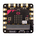
Klip Motor Driver for micro:bit
by Kitronik


The Klip Motor Driver for microbit allows you do more than just drive motors. It breaks out pins 0, 1, 2, 3V & GND from the microbit & connects to ZIP LEDS.
All of these pads are designed specifically for use with crocodile clips and banana plugs. That means no soldering or fiddling with connection blocks. Also, the pads have been designed and spaced to make it difficult to short two together with crocodile clips. This makes it ideal for use with younger children who can build buggies with little more than a couple of motors, a chassis, some elastic bands and the clip motor driver. .
It can run two DC motors simultaneously, both clockwise and counter-clockwise, and at varying speeds.
The board also features status LEDs. There are LEDs for board powered on, pins 0, 1, 2, 3 and also the two motor outputs. The motor indicator LEDs don't just monitor activity, they also indicate which direction each motor is running in, green for forwards and red for backwards. These LEDs don't just look nice, they are a great way of visually troubleshooting your code and they even allow you test your code without having to connect motors or devices to pins 0, 1, 2, 3.
Power is provided via the integrated battery supply (3 x AA, 4.5V), and the board then produces a regulated 3.3V supply which is fed into the 3V and GND connections to power the connected micro:bit, removing the need to power the micro:bit separately.
Kitronik have produced a set of custom blocks for the MakeCode editor to simplify using the Klip Motor Driver. To add them to the editor, select the cog icon in the top right of the editor. Then, select Extensions from the drop down menu and in the search bar type and enter Kitronik. Pick the tile from the list and the new blocks will be added to the menu in the editor. They've also included blocks within this package for driving any ZIP LEDs you attach to the board. These are primarily for allowing younger children to write code using blocks that are easier to use other coding blocks for addressable LEDs.
Note:
If the micro:bit is powered via its USB connector, and there are no batteries inserted, there will be no power at the 3V output connection – this is to provide some overcurrent protection for the micro:bit.
Features:
- Drive 2 x DC Motors simultaneously, both clockwise and counter-clockwise.
- It breaks out Pins 0, 1, 2, 3V and GDN (just like the main pads on the micro:bit itself).
- Connect to the pads with crocodile clips and banana plugs.
- There is also an out put design specifically for ZIP LEDs.
- Power is provided via the integrated battery supply.
- Output and motor driver status lights for troubleshooting and testing code prior to attaching motors and devices.
- Compatible with micro:bit v1 and v2!
Contents:
- 1 x Klip Motor Driver for the micro:bit.
Dimensions:
- Length: 72mm.
- Width: 70mm.
Requires:
- micro:bit
- Crocodile Clips.
- 3 x AA Batteries.
Resources:
Electrical characteristics:
- Operating Voltage (Vcc): 4.5V (3 x AA batteries).
- Regulated Voltage (supply BBC micro:bit): 3.3V.
- Max Current (@ rated Vcc):
- 6A (Total from switched supply)
- 150mA (Total from 3V output, allowing 100mA for BBC micro:bit)
- 15mA (Total from BBC micro:bit IO pins at any one time)
- Croc-clip Connections:
- 1 x 3.3V Output
- 1 x V Output (battery voltage)
- 2 x GND
- 3 x BBC micro:bit IO Pins (Pins 0, 1 and 2)
- 1 x ZIP LED Signal Output
- 2 x Motor Outputs (2 channels each)
We no longer stock this product
It's sad to say goodbye but sometimes we have to retire products to make way for new things.
You may still be able to buy this product directly from our friends at Kitronik - check out their website!
Shop with confidence – we've been serving the hobbyist electronics, Maker, and retro gaming communities since 2012.
- Satisfaction or refund guarantee
- Worldwide shipping via mail or courier
- 57,000+ customer reviews
- Secure website and payments
