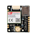
Clipper LTE 4G Breakout (SP/CE)
by Pimoroni


Clipper lets you receive and transmit data over 4G LTE cellular networks - perfect for remote or mobile projects.
WiFi is great, but sometimes you want your connected project to Just Work, wherever in the world it is. Perhaps you're going to a festival and don't know if there will be wireless connectivity to control your weird LED art installation. Maybe you're trying to get the tech in your shed to talk to your home automation software, but the range of your wireless router won't quite reach. Possibly you're attaching sensors to a distant beehive, canal boat, bicycle or other object with a remote or transient location?
Hooking your microcontroller up to cellular / mobile data could be your solution! Typically, transmitting sensor readings from or commands to microcontrollers doesn't consume much data compared to the needs of modern smartphones, so a small amount of pay-as-you-go data used like this goes a long way.
Clipper has a SP/CE connector on board - this means you can connect it easily to any SP/CE compatible microcontroller or add-on using a handy cable (of course, there's also pads if you'd prefer to solder wires to it). Click here to view all things SP/CE!
It also has an SMA connector for attaching an antenna. Cables and antennae are sold separately, or you can pick up a kit which includes them - just add a microcontroller!
Starter kit contains
- Clipper 4G LTE Breakout
- SP/CE cable
- Antenna (108mm)
Features
-
SIMCom A7683E 4G LTE module
- Frequency Bands: LTE-FDD B1/B3/B5/B7/B8/B20/B28
- Control Via AT Commands (SIMCom AT-Command Manual)
- SP/CE connector (8 pin JST-SH)
- SIM card slot
- SMA connector for attaching an antenna
- No soldering required (if you connect using SP/CE).
- Compatible with Raspberry Pi Pico / RP2040 / RP2350
- Compatible with Raspberry Pi computers
- Dimensions: 35x29x5mm (Antenna connector is 11mm tall)
Regional compatibility
The 4G LTE module on Clipper supports the following frequency bands:
B1/B3/B5/B7/B8/B20/B28
If you're planning on using the breakout outside of Europe we'd suggest first checking your local carriers offer 4G LTE on these bands. Networks in North America in particular only use a couple of these frequency bands, and so coverage may be limited.
Pinout and Schematic
- Schematic
- Pin functions (these functions are available via the SP/CE connector, and as unpopulated headers on the breakout):
- GND - Ground (this is pin 1 on the SP/CE connector, nearest the SIM card holder)
- PWRKEY - Power key pin, needs to be toggled low and then high to power up the module
- RX - UART input to breakout
- RESET - Reset pin, pull high to keep breakout active
- NETLIGHT - Output from LTE module, for blinking a LED when there is a network connection. It has a max output drive of 7mA and if you wire an external LED to this pin it should have a series resistor.
- TX - UART output from the breakout
- VDDIO - IO voltage input, 3.0 - 3.6V recommended for reliable IO. Low current consumption.
- VDD - 3.7V - 6.0V power input to the breakout (scroll down for current consumption info)
Getting Started
You can use Clipper with Raspberry Pi Pico (or other RP2040 or RP2350 based microcontrollers) using our custom MicroPython build, which has (experimental) LTE support built in:
- Download pirate brand MicroPython for RP2350 boards
- Download pirate brand MicroPython for RP2040 boards
- MicroPython example
You can also use it with a Raspberry Pi computer (if you wire it up to the correct pins) using Pi OS's built in `ppp` library - we found the article below helpful when setting it up:
Notes
- VDD current consumption info from our testing:
- Idle: 17mA
- Sleep modes: 0.12mA - 1.63mA
- Peak current consumption when transmitting: 700mA (the peak current is only reached for a brief moment, and the 440uF of capacitors on the breakout help to smooth the peaks)
- The average currents we saw when actively using the module were in the 50mA - 100mA range.
- The LTE module has quite a sensitive undervoltage circuit, so if your breakout keeps turning off randomly or when you try and do anything with it check your power supply and wiring is up to the task!
-
Board Only
PIM716£16.25 -
Starter Kit
PIM746£20.00
Add a LTE 4G antenna
You'll need to attach an external antenna to Clipper.
-
 LTE 4G Antenna+ £4.00
Add a SP/CE cable
You'll need one of these to connect your SP/CE device to your host.
-
 8 Pin JST-SH Cable (SP/CE)+ £1.50
Add a SP/CE host
Need something to connect this breakout to?
-
 Pimoroni Pico Plus 2+ £10.75
Shop with confidence – we've been serving the hobbyist electronics, Maker, and retro gaming communities since 2012.
- Satisfaction or refund guarantee
- Worldwide shipping via mail or courier
- 57,000+ customer reviews
- Secure website and payments


